How to ensure optimum performance of miniature DPA mics for wireless
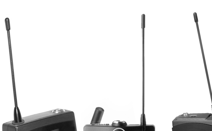
A bodyworn wireless microphone combines a small, wired microphone and a bodypack transmitter (TX). It is important to connect them correctly to ensure you capture the best sound.
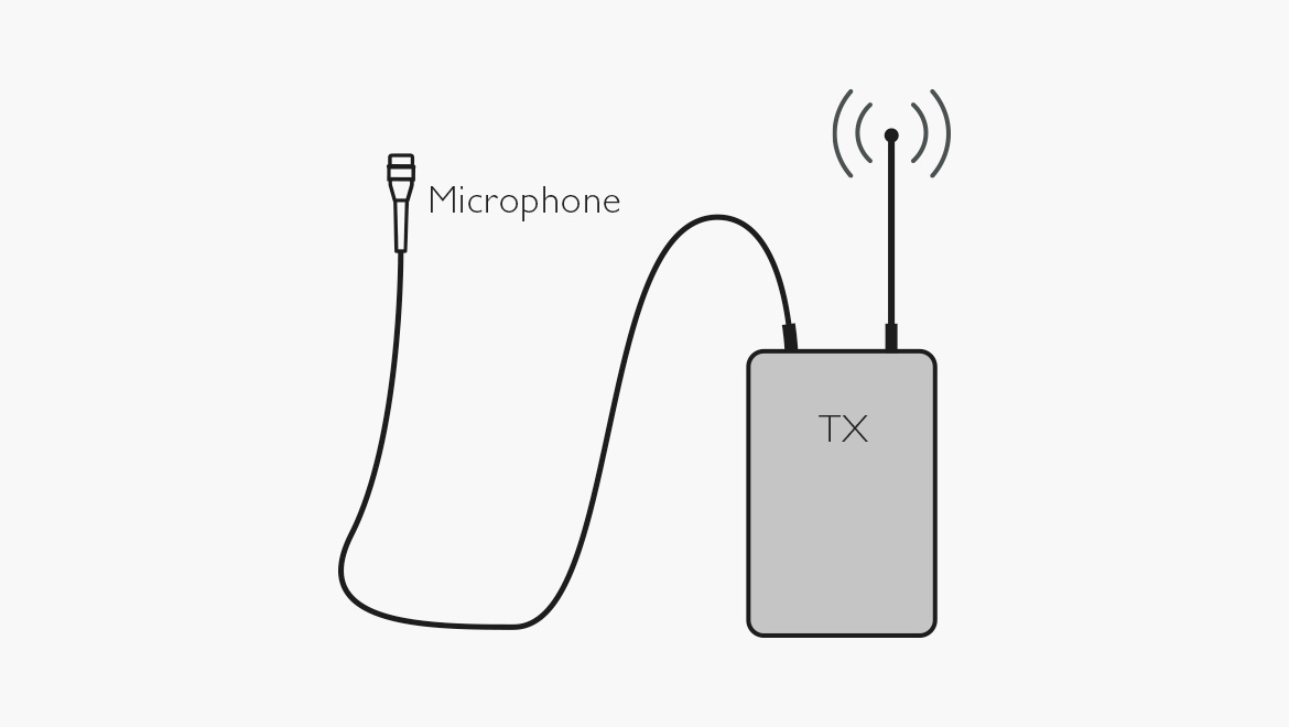
Figure 1. Bodyworn wireless microphone.
The microphone element is preferably an electret type due to its high audio quality, small footprint and no need for power. To make it work, however, it needs a powered, built-in amplifier/buffer/impedance converter. The transmitter's batteries should provide the power, often called "microphone bias" or "bias voltage”. The batteries' energy capacity is limited. Thus, most of the power should be saved for the transmitter itself, keeping it "on air" as long as possible.
Inside the microphone housing, a common solution
The electret microphone element produces a signal depending on the acoustic input. Unfortunately, the output of the microphone element cannot drive long cables and standard microphone inputs. To make it work, as mentioned, a buffer is needed. The most straightforward circuitry available inside the miniature microphone housing is – beside the electret element – a FET (Field Effect Transistor). The FET exhibits extremely high input impedance and relatively low output impedance, which is needed. The audio signal from the electret element controls the current through the FET. Even though the electret element can work without any kind of power supply, the FET needs external DC-voltage.
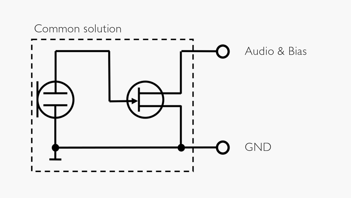
Figure 2. Common solution for miniature electret microphones, the electret element and the FET.
Controlling the current through a FET is a little like squeezing a water hose: If you tighten the grip, less water passes. If you press it too hard, the water stops running (in FETs, it is called "cut-off mode"). The simple FET-circuitry works relatively well if the cut-off mode is not reached. However, it has two disadvantages:
The current through the FET – the microphone's output – is not a completely linear function of the signal input. The result is a nonlinear dynamic range and some distortion. These non-linearity errors vary in different brands and models. Some manufacturers’ transmitters contain a built-in correction network for the linearization of the FET. Most do not.
Due to the supplied bias voltage's polarity, the output goes negative when the sound pressure on the microphone diaphragm goes positive. Common audio standards state that microphones should produce positive voltage when positive pressure is present at the front of the diaphragm. Some manufacturers correct this by reversing the transmission system's polarity. See Mic University article: The polarity of wireless belt-pack systems.
Inside the mic housing, the DPA solution
All DPA’s miniature microphones have a very advanced circuitry that ensures high sound quality and a high degree of versatility. CORE technology was designed to enhance audio quality by reducing distortion and extending the dynamic range of miniature microphones. Building on the success of CORE, the new CORE+ technology takes these improvements even further by eliminating distortion within the increased dynamic range achieved with CORE*.
DPA miniature and subminiature microphones have these features:
- Positive output for positive-going sound pressure, i.e., in-phase.
- Fully compensated electronics providing the lowest distortion possible at all levels.
- Each mic is trimmed to maximum performance and does not need a specific brand TX for better performance.
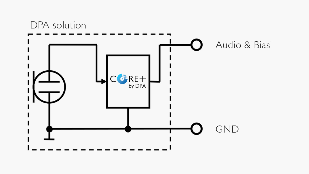
Figure 3. Solution for DPA miniature microphones with CORE by DPA technology or CORE+, ensuring a high degree of linearity and low distortion.
By miniaturizing the advanced electronic circuitry implemented in CORE by DPA technology, it can be contained even in the small 3 mm capsule housing of the subminiature microphones.
How much voltage?
The magnitude of the bias voltage determines the possible level of the audio signal. The signal can never exceed the operating voltage. So, if you want an audio signal of a given amplitude, a sufficient operating voltage (bias) should be available.
The bias voltage available in most transmitters is in the range of 5-7 volts. However, a few brands provide only 2-4 volts. DPA miniature microphones (lavaliers, headsets and instrument mics) need 5-10 volts to work correctly.
What happens if the voltage is too low?
As mentioned, the output signal depends on the supplied DC voltage. If it is too low, it may result in asymmetrical clipping of the audio signal above a certain level [see figure 4]. The result is distortion, the lower the DC voltage, the more distortion at increased levels.
If the available bias voltage is, say, 4 or even 3 volts, the microphone still works. But the acoustic input must be reduced and kept below a limit, lower than the usually specified max SPL; this is to avoid distortion. In practice, a low bias voltage (3-4 volts) means the max input signal must be kept at approximately 6-10 dB below the specified max value.
In general, if the SPL is below 110 dB, 3-4 volts bias can be accepted without too much signal degradation. But remember, the microphone no longer meets full specifications.
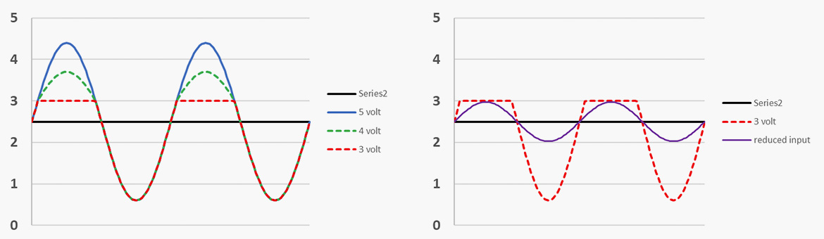
Figure 4. Output as a function of operating bias voltage, 5, 4 and 3 volts. Left: At max specified SPL (distortion is introduced when the bias voltage is reduced below 5 volts). Right: At max possible SPL (reduced input).
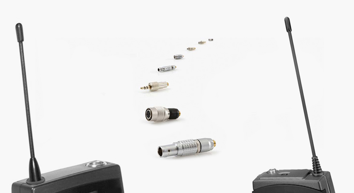
The role of DPA adapters
As standard, earlier a MicroDot Connector – now the MicroLock® Connector terminates DPA miniature and subminiature microphones.
The MicroLock connector is backward compatible with the MicroDot. However, only when both the male and female parts is MicroLock®, can the connection be locked. The sleeve must be pulled and turned for release.
Different manufacturers of transmitters use different connectors for microphone inputs. To make DPA microphones (4000 and 6000 Series) fit the various brands, an adapter is a practical solution. The MicroLock connector then adapts to the actual other connector type and allows you to use the microphone on various transmitter types, now and in the future.
The adapter also ensures the optimization of the voltage/current available from a specific transmitter. Some adapters have built-in resistors. These components are present to provide the correct bias for the microphone. This is one reason microphones may not work if the cable is soldered directly into a random connector. (On the product pages, you can see diagrams revealing the inside of the adapters).
The 2061 Omnidirectional Miniature Microphone is, however, born with TA4F (Mini-XLR), 3-pin LEMO or Mini-Jack.
Connection, 2-, 3- and 4-pin
Different brands use different connector configurations, including 2-, 3- or 4-pin variants.
2-pins: In a 2-wire connection, it may seem that one wire is missing. What you need is a voltage supply plus ground and audio out plus ground. In the 2-wire connection scheme, one wire is used to supply the voltage to the microphone and receive the audio from it.
So, in the 2-pin connection, the wire carrying audio and bias is connected to one pin, and the ground/shield is connected to the other.
All DPA miniature and sub-miniature microphones (except for 2061) are 2-wire types. MicroLock® is a 2-pin connector.
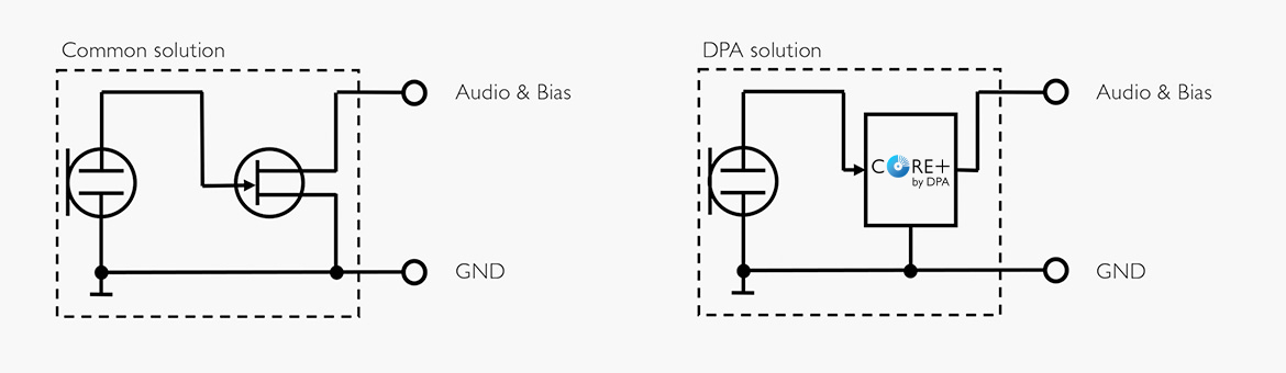
Figure 5. 2-pin connection of 2-wire microphones, whether it is traditional FET types (left) or CORE/CORE+ by DPA versions (right).
3-pins: The connection for the traditional 3-wire microphone is straightforward: One wire for the voltage supply, one for audio out and one for the common ground.
In contrast to the 2-wire single FET solution, the 3-wire connection offers the possibility of positive output for positive-going sound pressure, i.e., in phase. (See schematics below).
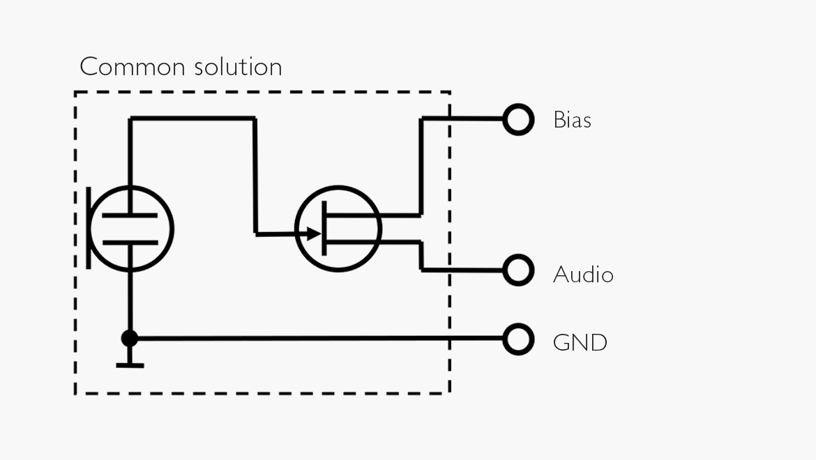
Figure 6. Conventional 3-wire FET circuitry with in-phase output. Connector types: Mini-Jack, 3-pin LEMO.
4-pins: In a simple design, with only one active component (the FET) in the mic, some manufacturers build a simple compensation circuitry in the transmitter using a 4-pin connection. The compensation does not work equally well for all microphones but is specific for a particular mic and TX combination. A "one-size-fits-all" solution is not optimal as the microphone and transmitter should rather be paired one-to-one.
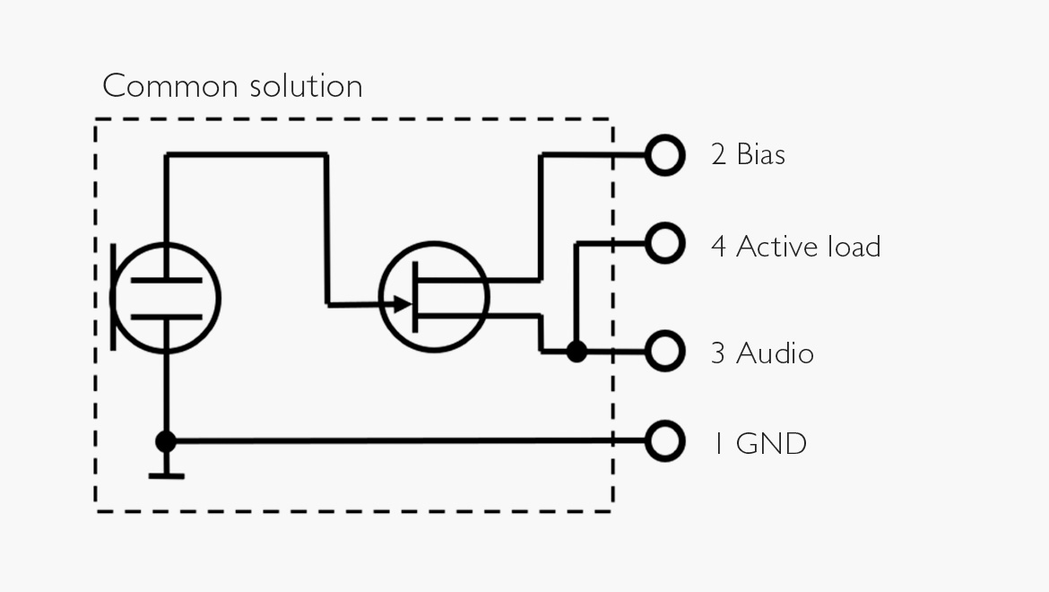
Figure 7. An example of a 4-wire connection with compensation for single FET circuitry. Connector: MTQG/TA4M.
DPA miniature and subminiatures should never be connected to a compensational circuitry as it may reduce the already optimized output. In the adapter connection scheme of DAD9010 (MicroLock® to 4-pin connector) which is shown below, pin 4 (for active load) is not connected.
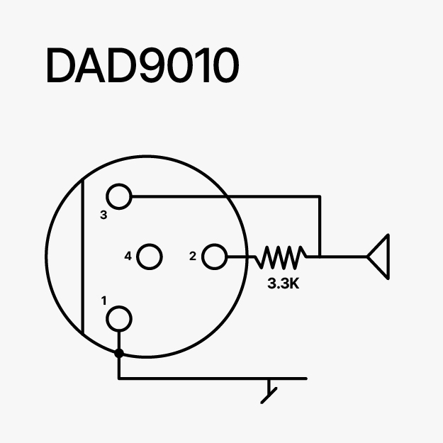
Figure 8. DPA adapter for 4-pin connections, DAD9010.
Conclusion
DPA miniature and subminiature microphones are linear by design. Feed them with 5-10 volts and they will work correctly. Avoid "linearization circuitry" in any transmitter. Make sure you choose the right connection scheme so that the mics work perfectly.
Pinout diagrams
See the pinouts for the DPA adapters below and see all our adapters here.