Polarity, phase and delay
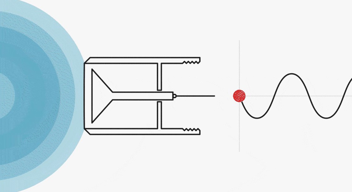
The waveform of an audio signal exhibits a positive segment above the zero line and a negative segment below. Sometimes the waveform looks symmetrical and other times asymmetrical. Usually, the waveform’s shape and polarity doesn’t matter until we begin to mix the signals, i.e., when we have signals from two (or more) microphones that we want to combine or perhaps distribute for spatial imaging. Then, it is important to understand the terms polarity, phase and delay. This article describes the three terms with regard to microphone techniques and technology.
Polarity of microphones
It is a convention that a microphone’s polarity must be known. What is the polarity of the outgoing signal in comparison to the incoming? This is described by international standards. The polarity is sometimes indicated by a colored dot on the microphone connector that delivers positive-going voltage by an inward movement of the diaphragm. Or, in the case of balanced XLR connections, it is decided that pin 2 always represents the in-phase signal of the acting sound pressure. So, rising pressure on the diaphragm, moving the diaphragm inward, provides a rising positive voltage on pin 2. This is true for balanced condenser microphones for professional audio (not necessarily measurement microphones), while dynamic microphones behave a little differently (see later in this article).
Change of polarity
Changing the polarity is a simple swap of the negative part becoming positive and the positive part then becoming negative. The signal is inverted (“INVERT” is a function of many DAWs). Or, in a mathematical fashion, the signal is multiplied by “-1”. See Figure 2.
Sometimes, it is said that the phase is shifted by 180°. This is, however, not exactly correct. A phase shift requires a time shift, i.e., a delay, which is not involved in swopping polarity. On the other hand, after inversion, the signal is now 180° out of phase.
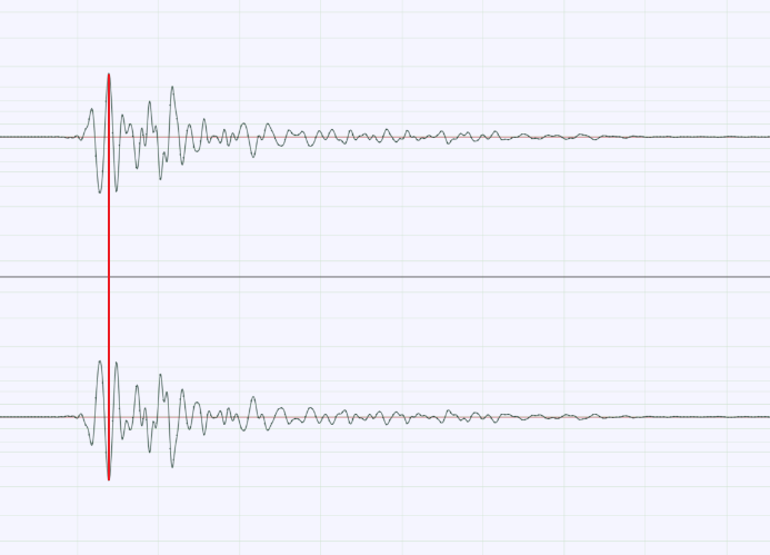
Figure 2. The lower signal is an inverted version of the upper.
ShapeIn many mixing devices and preamps (both hardware- and software-based), changing the polarity of the input signal is possible in each channel. The Greek letter φ [small letter phi] on the button indicates the function of inversion. Sometimes, it looks like the letter Ø.
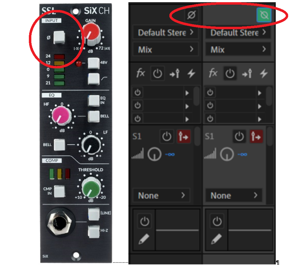
Figure 3. Left: Physical channel strip with polarity button (Solid State Logic). Right: DAW mixer channels; in this case, the letter Ø is mirrored when the polarity switch is activated (Adobe Audition).
Microphone rear-lobe polarity
Directional microphones, like supercardioids, hypercardioids, or figures-of- eights are recognized by their rear lobes, which can be read from the polar plot. These microphones pick up frontal sound and, by various amounts, sound from the rear. However, the polarity of the sound picked from the rear is inverted. The explanation is predominantly related to which side of the diaphragm is first hit by the sound. A frontal incident moves the diaphragm in one direction, whereas a rear incident of the same sound moves the diaphragm in the opposite direction.
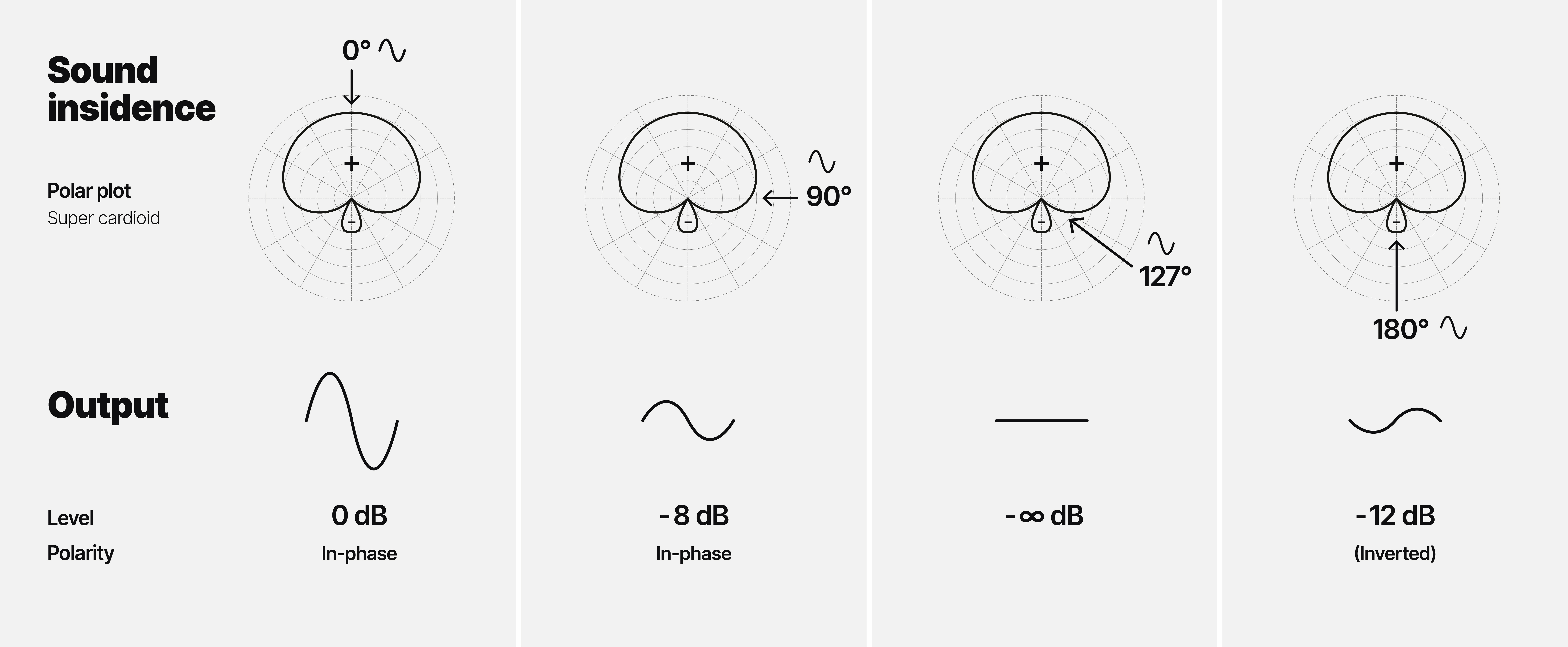
Figure 4. Output from a supercardioid microphone for different angles of sound incidence (0°, 90°, 127°, and 180°).
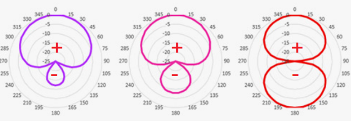
Figure 5. Polar plot of supercardioid, hypercardioid, and figure-of-eight with marked polarity ”+” or “-“.
Phase
Phase can only be expressed if the actual waveform is compared to a reference or another waveform – and at a given frequency. The phase shift occurs due to a shift in time, a delay. The time shift may stem from two microphones’ different distances to a sound source. Or due to the application of a delay line. Or due to the physics of a given electrical filter.
Usually, we describe a phase shift by the so-called phase angle in the range of ±180°. Sometimes, the angle is more than that, and we may rather describe the phase shift as a delay at the given frequency.
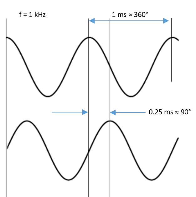
Figure 6. Two sine waves (1 kHz) shifted/displaced 90° (0.25 ms).
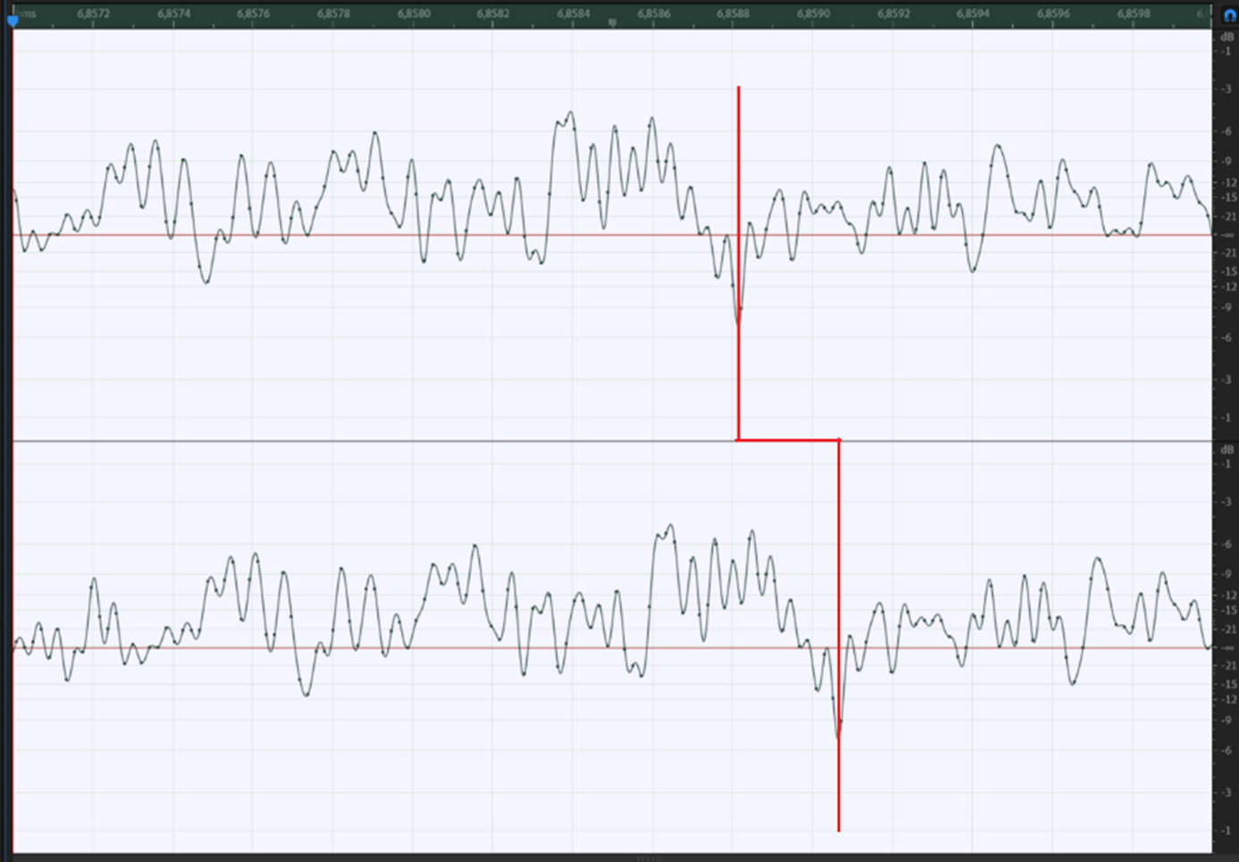
Figure 7. 2-channel broadband noise, lower channel displaced (delayed) by 0.25 ms
In a complex audio signal containing many frequencies, the phase of the individual frequency components influences the resulting waveform. Below are two signals containing five frequencies (one fundamental and four harmonics). Imagine the five frequency components being “downmixed” or summed to the final single waveform.
To the left, every frequency component starts at 0°, and to the right, every frequency component starts at 90°. If the fundamental frequency is 1 kHz, the second harmonic is 2 kHz, the third is 3 kHz, etc.
The duration of one period of 1 kHz is 1 ms (1/1000 s). A phase shift of 90° (a quarter of a period) equals a time shift of 0.25 ms.
The duration of one period of two kHz is 0.5 ms (1/2000 s). A phase shift of 90° (a quarter of a period) equals a time shift of 0.125 ms.
As shown, the time shift of a constant phase shift varies with frequency. Further, the resulting waveforms are very different even though containing exactly the same frequency components. (However, they sound the same if reproduced in a linear system, as the ear only to a minor degree is sensitive to phase).
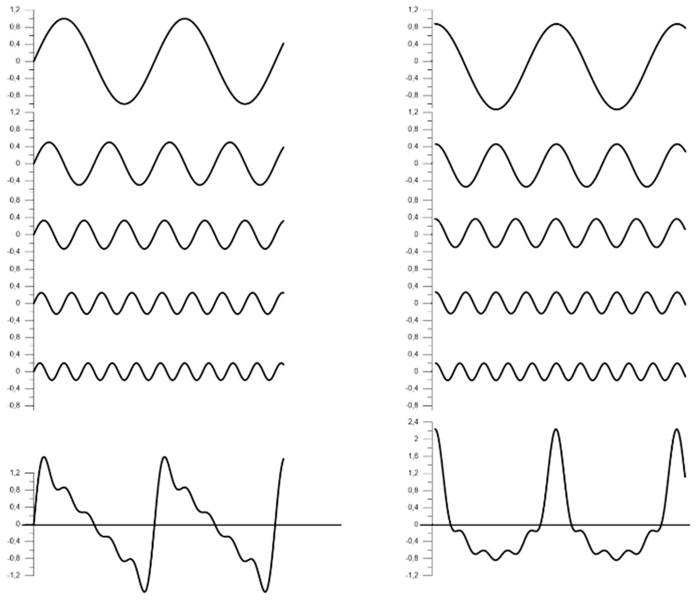
Figure 8: Two curves containing five frequency components each. The left starts @ 0° (left) and the right starts @ 90°.
Variable phase shift
In audio processing, we experience phase shifts all the time. Most equalizers or equalizing circuits may exhibit frequency-dependent phase shifts. An example is the 2017 Shotgun Microphone. A 60 Hz low-cut filter (3rd-order Butterworth) is implemented. Figure 9 shows the phase response of the filter as calculated. Figure 10 shows the phase response of the 2017 Shotgun Microphone as measured (including the built-in low-cut).
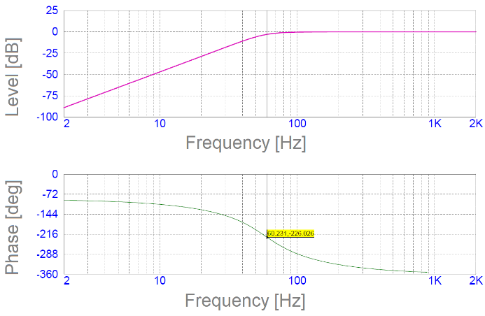
Figure 9. Frequency response and phase response of built-in, low-cut filter for DPA 2017 Shotgun Microphone.
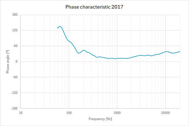
Figure 10. Phase response of DPA 2017 Shotgun Microphone with built-in, low-cut filter.
Delay
As already shown in Figure 7, a delay “stores” the signal for a period of time and releases it again. Or the propagation of sound is dependent on the medium in which the sound moves. For instance, the sound is slower in the air compared to a wire.
An electronic device made for delaying audio signals is often applied in loudspeaker systems to make sound arrive simultaneously from different loudspeakers at different distances.
Group delay
Group delay is almost the same as a delay. However, it only concerns “a group” of frequencies around a specific frequency in an audio signal. Group delay is seldom achieved on purpose but is what happens using various electronic circuitry.
Phase response of microphone transducers
The phase response of microphones is primarily related to the transducer principle applied. Regarding modern microphones, this concerns either condenser microphones or dynamic microphones.
The starting point is:
The condenser (omnidirectional/pressure) microphone is in phase with the acoustic signal.
The dynamic microphone (ribbon or moving coil) is shifted by 90°.
All microphone diaphragms have a resonance frequency (just like a drum). Resonances may introduce phase shifts. However, the diaphragm resonance is not the only resonating phenomenon in microphones. Cavities between the diaphragm and the grid may also have influence.
Figure 11. Output vs. sound pressure. Left: a condenser microphone, right: a dynamic microphone.
Conclusion
Polarity, phase and delay are more or less related terms. However, as explained in this article, there are differences that one should be aware of.