The basics about distortion in mics
We do not want any unintended distortion in our recording chain. Unfortunately, there is usually some form of distortion present although it is below the threshold of audibility. When setting up the recording chain, the individual links of the audio chain may each contribute to the summed distortion, which eventually may become audible.

Before considering the amount of distortion, we must define the various forms of distortion we meet in our equipment – and in this case – with a special focus on microphones. We must also consider the hearing system (the ears and brain), which sets the real limits for audibility.
Distortion – linear or nonlinear?
When a signal passes from input to output, any change in that signal (i.e., the signal’s waveform) can be regarded as distortion. By and large, all distortion is nonlinear. However, the change in magnitude might be considered as "linear distortion" as it can be corrected at a later stage. The delay of a signal sometimes is also regarded as linear distortion since the waveform is intact, just delivered a little later.
Because of these definitions, any purposely-applied equalization, any change of bandwidth and any limitation, causes a kind of distortion. However, we should be aware of unintended distortion and how it affects the perceived sound quality.
Distortion – where does it come from?
Distortion occurs due to limitations and other nonlinearities in a system. Even the sound in the air has a limitation to its magnitude. When the sound pressure level exceeds 194 dB SPL, there are no more air molecules to form the negative part of the soundwave as it reaches the point of a total vacuum. (See the figure below).
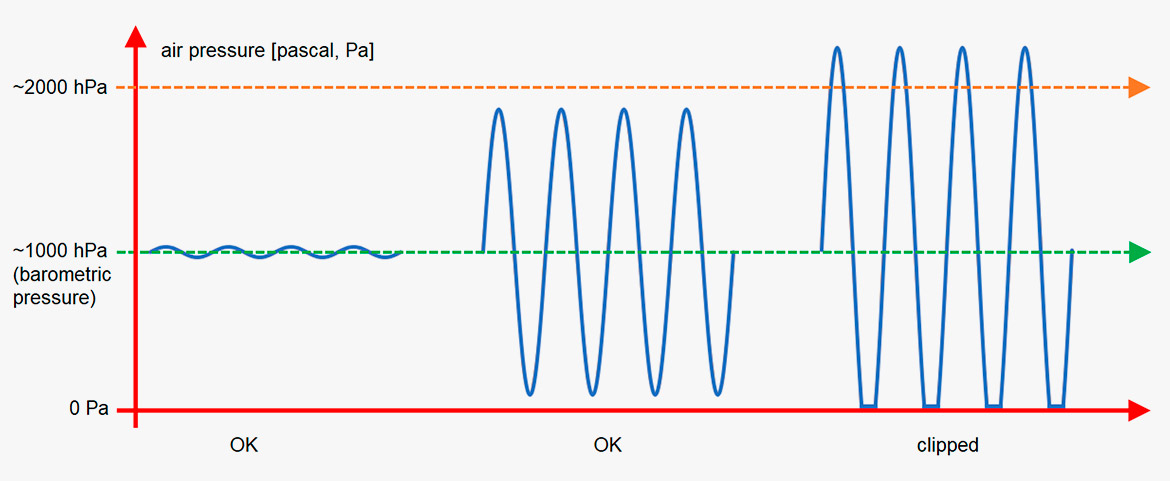
Figure 1. Distortion in air when the SPL exceeds 194 dB.
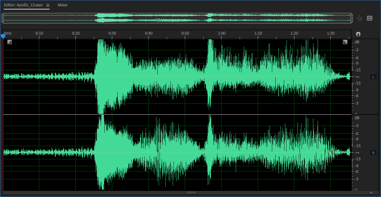
Figure 2. Sound file: Apollo 13 lift off. After 60 sec you can hear what sounds like heavy distortion. That is distortion in the air. If you look at the waveform (above), you can see that the positive parts are higher than the negative ones.
Distortion in microphones
A major component of the microphone is the diaphragm. If the microphone is a condenser type, the diaphragm has a position in front of a backplate. The space between the two is in the range of 20-50 µm.
When placing the microphone in a high-SPL situation, it is obvious that there is a limit to the excursion of the diaphragm, at least when pushed in the direction of the backplate. Also, the diaphragm material itself has a limit to how "stretchable" it is in either direction.
Any condenser microphone needs an electronic interstage that converts the high impedance of the transducer into a relatively low impedance to feed longer cable-runs. This electronic design may be a source of non-symmetrical behavior. (CORE by DPA is a succesful attempt to improve on this).
Although manufacturers are constantly trying to improve the microphones, there exist limits to the microphone systems that eventually may cause distortion.
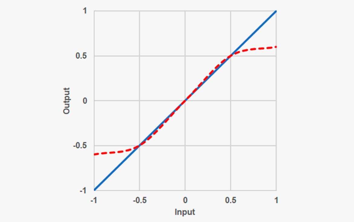
Figure 3. A way to describe nonlinearities of a system. The blue curve: No limitations. The red dashed curve: Limitations in the system.
How to specify distortion?
According to the IEC standards [1, 2], the amplitude nonlinearity is expressed by three measures: total harmonic distortion (THD), distortion of the nth order, and difference frequency distortion of second order. What do these terms mean?
Total Harmonic Distortion: A pure sinewave consists of one and only one frequency. When distorted (typical by clipping), additional frequencies – integer multiples of the fundamental tone - are generated. If the microphone is placed in a sound field of a pure tone (e.g. 1 kHz) the distortion products – the harmonics generated – include frequency components at 2 kHz, 3 kHz, 4 kHz, etc. normally decreasing in level. (In case of symmetrical clipping, just uneven harmonics are generated, 3rd, 5th, 7th, etc.).
THD measurement is carried out by measuring the amount (RMS) of all the higher order harmonics as a percentage of the level of the fundamental frequency. The result should preferably be <1% in the major part of the dynamic range. 1% harmonic distortion means that the unwanted frequency components have a level 40 dB below the fundamental frequency. This a limit preferred by many microphone manufacturers. This is also a "visual" limit as this amount of distortion becomes visible on the waveform, for instance monitored on an oscilloscope or when recorded and viewed in the DAW.
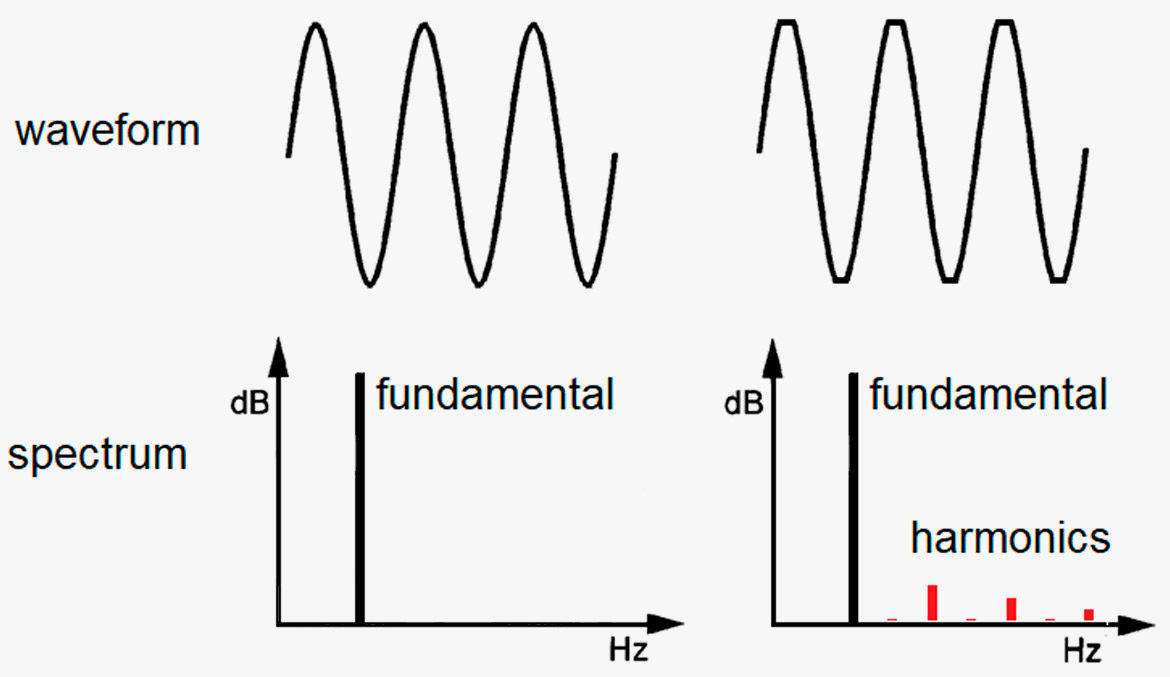
Figure 4. THD is the portion of harmonics that occur due to nonlinearity, for instance clipping.
In practice, the THD is difficult to measure at low to medium SPLs as the loudspeaker normally exhibits a higher distortion compared to the microphone. However, when approaching levels close to the microphone’s max SPL limits, the THD may increase rapidly.
Distortion of the nth order: This is in principle the same as THD, except that harmonics are individually measured and quantified. Sometimes the third harmonic is of specific interest because it, by symmetrical clipping, is the harmonic representing the highest level of all harmonics generated.
Difference frequency distortion: For this measure, two pure sinewave tones are applied at identical levels. The IEC-standard defines the distance between the frequencies as 80 Hz. An example of frequencies is 1000 Hz and 1080 Hz. However, a sweep over a wider range may apply. A difference distortion generates sum and difference frequencies (i.e. 1000 Hz and 1100 Hz creates a 100 Hz difference frequency). These frequency components are measured and quantified as a percentage of the fundamental frequencies.
It must be noted, that it's absolute fine to apply a standardized methodology for the quantification of distortion. However, the standards only take a small selection of possible forms of distortion into account. In real life, signals are far more complex and so are the distortion components.
What is audible?
To find what matters we must look at psychoacoustic research. Here are some phenomena that influence the perceived sound quality.
Threshold of hearing: Our hearing system has a natural lower limit. This limit varies with frequency. At low frequencies, the level of threshold is rather high. In the frequency range of 2-4 kHz, the level of threshold is low. See figure 5.
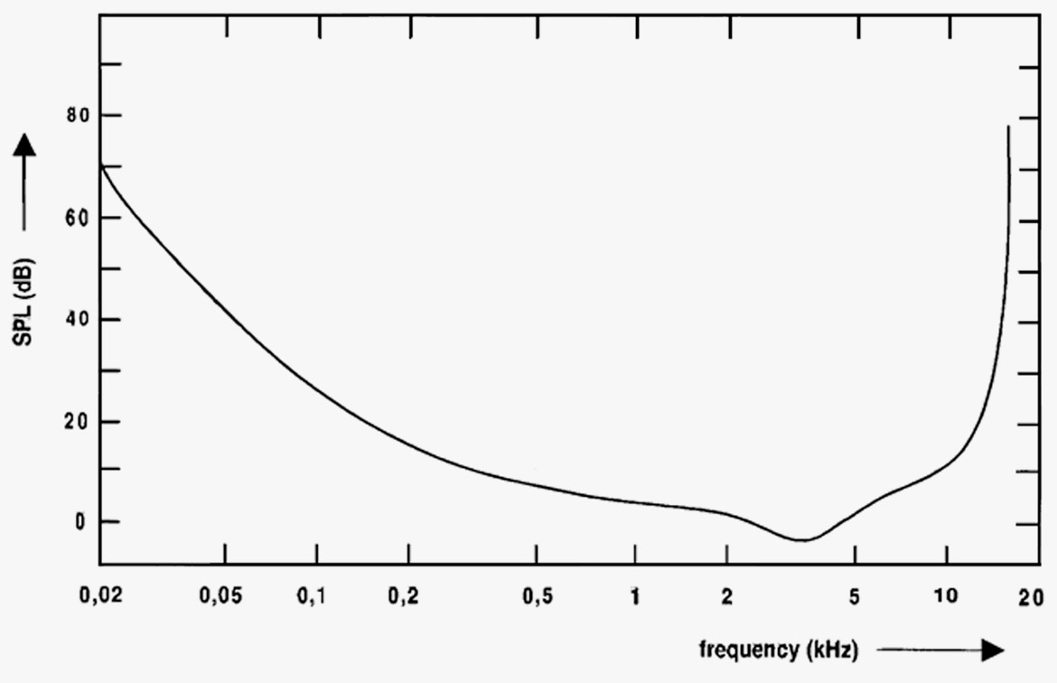
Figure 5. The curve indicates the threshold of hearing (people with normal hearing). Humans are not able to hear sound below the threshold. Please notice that humans do not hear low-level low frequencies very well.
Masking: When the ear is exposed to sound energy in a specific frequency range, a masking of the surrounding frequencies is created. This masking especially works at higher frequencies.
The illustration below shows the masking curves of a 1 kHz pure tone at various SPLs.
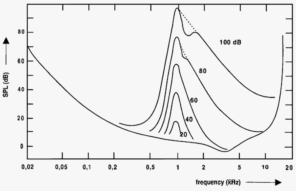
Figure 6. The diagram shows the masking curves of a 1 kHz pure tone at various SPLs.
This means, that very often the distortion components become inaudible due to masking.
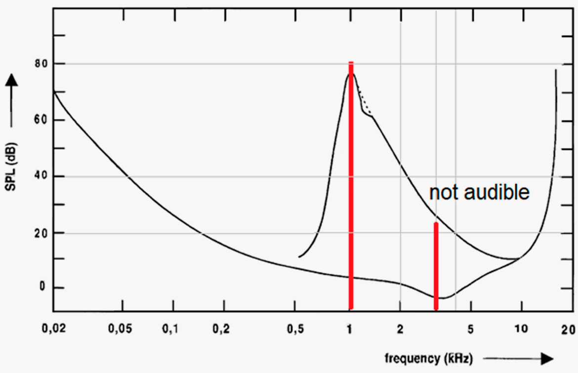
Figure 7. The 3rd harmonic (3 kHz) of the 1 kHz tone is inaudible due to masking even though the distortion is 5%.
Regarding difference frequency distortion, the frequency components below the masking frequencies become the most audible. This is also related to the fact that the difference tones are not necessarily musical and are therefore perceived as more annoying.
The masking effect is essential for all bit-reduced audio formats. Here, the distortion may be high and the signal-to-noise ratio low. However, we (listeners in general) often accept the way it sounds.
Distortion of the ear: The ear itself generates distortion. This phenomenon especially exists at higher SPLs. The ear has its best resolution at lower SPLs.
This phenomenon is heard when listening to two tones that are almost equally loud. Depending on the frequency interval between the two tones, a third tone can be heard. For instance, if you hear two tones with the interval of one fifth, C3 and G3 (131 Hz and 196 Hz) your ear will create the difference tone of 65 Hz (C2, which is one octave below the C3. A fact used when building pipe organs to create "artificial sub-voices").
Below is an example of intermodulation or difference frequency distortion. Two tones are generated. The ear then produces difference tone distortion. However, only the tones below the real tone are perceived – due to masking.
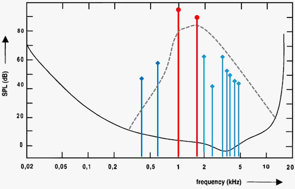
Figure 8. Distortion in the ear: Frequency components occurring due to two frequencies: 1 kHz and 1.6 kHz. Only the two components below 1 kHz become audible.
Conclusion
In general, there should be no distortion in your microphones. However, in reality there is some. Measures like THD and difference frequency distortion measurements do not tell the full story. However, the numbers in the specs can be regarded as an indication of how "healthy" the design is. What is perceived by the ear is rather complex because the ear produces distortion itself. Despite the numbers, the more distortion in your microphone, the muddier and more unclear the sound gets in your recording.
References
[1] IEC 60.268 Sound System Equipment, part 2: Explanation of general terms and calculation methods.
[2] IEC 60.268 Sound System Equipment, part 4: Microphones.
[3] Geddes, Earl R.; Lee, Lidia W: Auditory Perception of Nonlinear Distortion - Theory. AES 115th Convention Paper 5890. 2003.
[4] Geddes, Earl R.; Lee, Lidia W: Auditory Perception of Nonlinear Distortion. AES 115th Convention Paper 5891. 2003.
[5] Toole, Floyd E.: Sound Reproduction - The Acoustics of Loudspeakers and Rooms. Focal Press 2008. ISBN 978-0-240-520094

